Customer:
I need to connect 3 servo motors and a 16x2 LCD display to a Croduino STM32 for a control panel project (speedometer). Which pins should I use for these components?
Original message (Croatian)
Poštovani, dobar dan. Za potrebe projekta u kojem moram napraviti kontrolnu tablu (brzinomjer), trebam spojiti 3 servo motora te 16x2 LCD display na CroduinoSTM32.
Na koje pinove treba spojiti navedene komponente?
Lp,[name removed]
Originally submitted via email support on 23 March 2022. Migrated to the forum for community visibility.
Soldered Support:
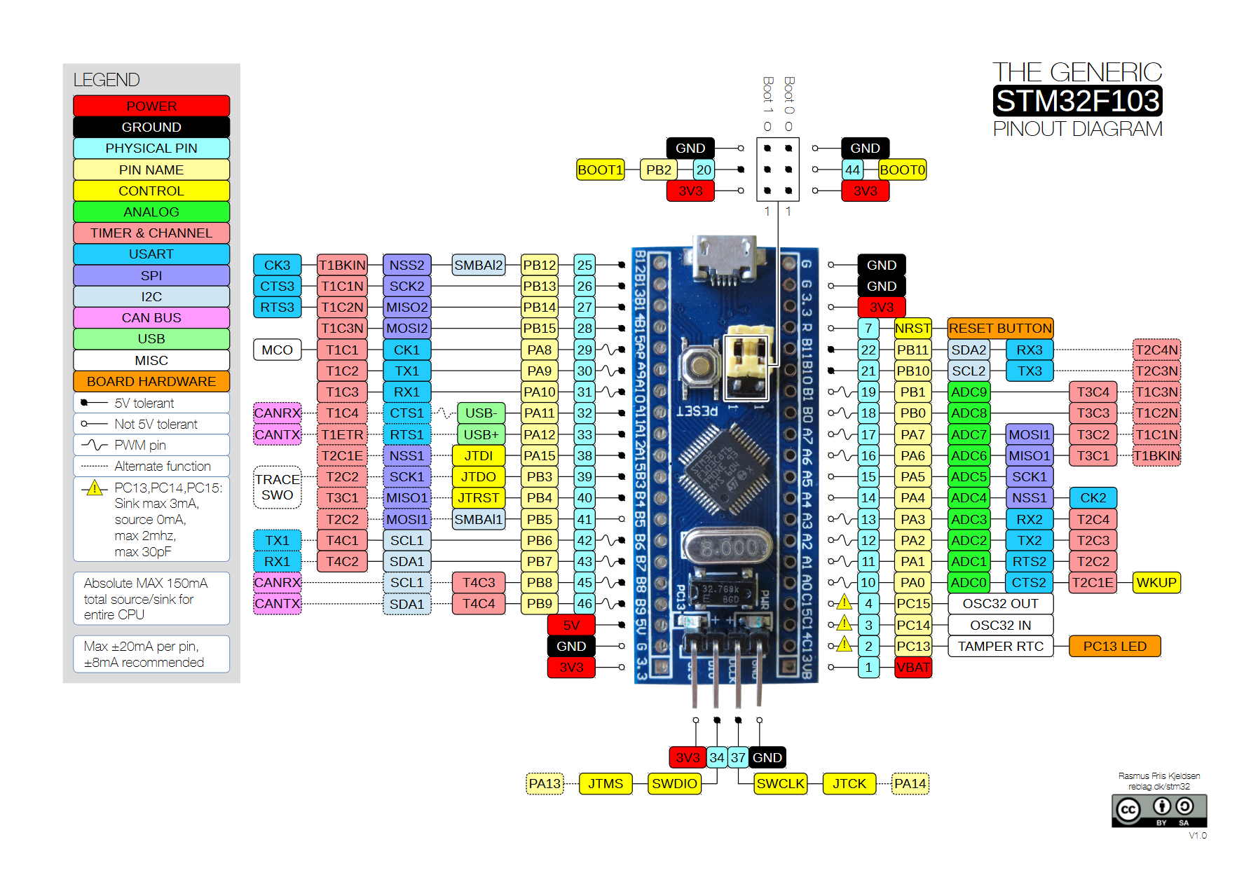
Select pins according to your needs. For servo motors, the pins must be PWM, so you can look at the STM32 board pinout and select 3 PWM pins from it. For the display you need more pins, but our Knowledge Base has information on how to connect and use it.
The best approach is to take the LCD, connect it and test it. Of course, in your code you need to set the pins that the LCD is connected to, and it should work. Once you have a working screen, you can connect one motor and adjust it, then finally assemble the whole project and write the code. This way you ensure that everything works individually and you avoid many problems that can arise if you connect everything at once and something doesn’t work.
Original message (Croatian)
Pinove odaberete prema onome što vam treba. Za servo motore pinovi moraju biti PWM tako da možete uzeti pinout za STM32 pločicu i prema njemu odabrati 3 PWM pina. Za ekran treba malo više pinova, ali imate u našem KKM-u kako ga spojiti i koristiti.
Najbolje je da uzmete LCD, spojite ga i testirate, naravno u kodu trebate postaviti pinove na koje je LCD spojen i trebao bi raditi. Kada imate ekran koji radi možete spojiti jedan motor i njega podesiti te onda na kraju složiti cijeli projekt i napisati kod. Tako ste sigurni da vam sve radi pojedinačno i otklanjate mnoga pitanja koja se mogu pojaviti ako sve spojite odjednom i nešto ne radi.
Customer:
How do I identify PWM pins on this diagram?
Original message (Croatian)
Kako raspoznati PWM pinove na ovom dijagramu?
Lp, [name removed]
Attachment omitted in migration: STM32-shema.png
Soldered Support:
The schematic does not clearly show PWM pins as they are not marked in any special way. At https://upload.wikimedia.org/wikipedia/commons/9/90/Stm32f103_pinout_diagram.png there is a pinout diagram for a similar board that uses the same microcontroller, just with a different form factor, but the pin functions are the same. PWM pins are marked with ~ on the pinout (for example, PA8, PA9 and PA10).
Original message (Croatian)
Sa sheme nije moguće vidjeti PWM pinove jel nisu nikako posebno označeni. Na linku ( https://upload.wikimedia.org/wikipedia/commons/9/90/Stm32f103_pinout_diagram.png ) je pinout slične pločice koja koristi isti mikrokontroler samo je oblik drugačiji, ali funkcionalnosti pinova su iste. PWM pinovi su označeni s ~ na pinoutu (npr. PA8, PA9 i PA10).