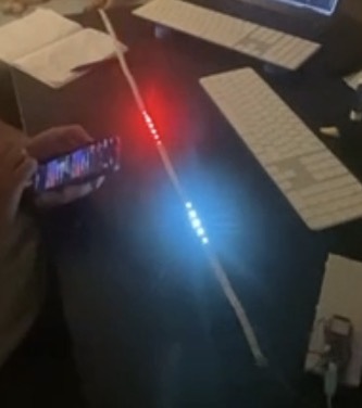
I am a hardware noobie starting to work on a small project I’d love feedback on.
The idea:
Swimmers can’t easily see a phone or watch underwater, so instead of a normal pace clock, I’d like to build a moving light pacer composed of an addressable LED strip along the pool floor with a lit “dot” (plus a short fading trail) that travels down the lane at a set target pace. Each swimmer just has to keep up with the light. It reverses direction at the wall so it keeps pacing on the way back too.
After some internet research, here is my proposal:
25m pool, LED strip run inside a 30m clear acrylic tube sealed at both ends (the tube does the waterproofing, so the strip itself doesn’t need full underwater potting).
6×5m addressable LED strips (12V, WS2811), data chained in series, power injected separately via a 12AWG spine wire at each segment to avoid voltage drop over the run.
Controller: NULA Max RP2350 — picked for the RAM headroom (frame buffer for ~900 LEDs is trivial), PIO for clean long-strip timing, and built-in WiFi/Bluetooth.
Power: battery-based (LiFePO4, 12.8V) rather than mains — keeps mains electricity away from the pool entirely, only low-voltage DC goes near the water.
Control: the board runs as its own WiFi access point with a small web page, so I can set pace from my phone without needing pool WiFi or an app.
Using connectors instead of soldering, since I don’t have soldering experience or equipment at home yet.
Do you have any suggestions? Your feedback would be highly appreciated. And if any of this is available in your store — or you can point me to reliable suppliers for the rest — that would be amazing
Benjamin
p.s. Last suggestions I got from you guys regarding accelerometers worked like a charm. Thank you!
Thanks for writing in, and great to hear the accelerometer advice worked out.
The concept is good and your reasoning is better than you give yourself credit for. Keeping mains away from the pool and running only low voltage DC near the water is the right call, power injection along a 12AWG spine is correct, and running the board as its own access point will save you a lot of grief with pool WiFi. Here is what I would change or check before you order anything.
Your power budget is much smaller than you probably assume. Since only the moving dot and its trail are lit, you have maybe 15 pixels on at any moment. That is a few watts, not the 400 W a fully lit strip would draw. A battery pack is completely realistic here.
Buoyancy is your biggest unsolved problem, and you did not mention it at all. A sealed 30 m tube full of air will float, no matter how you weight the ends. You need distributed ballast along the whole length, or you need to fill the tube with something other than air.
There is no such thing as a 30 m acrylic tube. It comes in 1 to 3 m lengths, so you are looking at ten or more joints, each of which has to be watertight and optically clear. Add condensation inside a sealed tube, thermal expansion, and the fact that acrylic is brittle and people will step on it. Polycarbonate is a safer material if you go this route.
Check the resolution before you buy. WS2811 at 12 V groups three LEDs into one pixel, so your smallest step is about 10 cm, not 3.3 cm. Over 25 m that gives you roughly 300 addressable points. Probably fine for pacing, but worth knowing in advance.
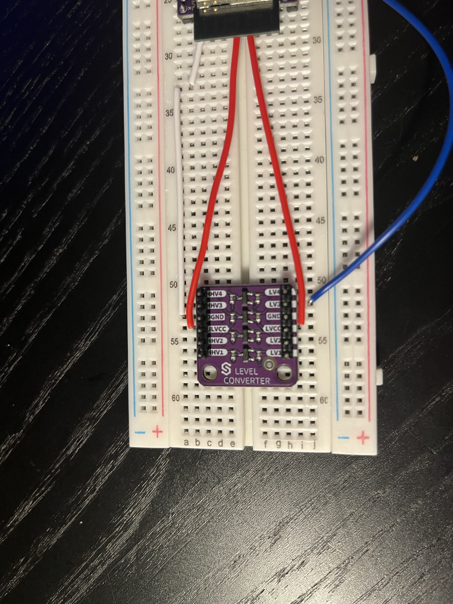
You are missing a level shifter. The board outputs 3.3 V logic and WS2811 wants roughly 0.7 x VDD, so without one you will get random flickering. Ours is 4 channels for 2.50 EUR: Logic Level Converter Board – Soldered Electronics
On the controller, I would suggest the NULA DeepSleep ESP32-S3 instead of the RP2350: NULA DeepSleep ESP32-S3 Dev Board - 7µA Low Power – Soldered Electronics The setup is simpler for a first project, since the WiFi access point and web server examples are very mature on ESP32, and power consumption is lower. It has 8 MB PSRAM, so a 900 pixel frame buffer is nothing, and the RMT peripheral drives long strips without any timing trouble. A USB C cable is included.
How are you planning to power the controller itself? This matters, because the battery connector on all our boards is meant for a 1S Li-Ion or Li-Po cell at 3.7 V. You cannot connect 12.8 V LiFePO4 to it. You will need a small DC to DC converter stepping 12.8 V down to 5 V for the board, or a separate 1S cell just for the electronics.
Put a fuse directly on the battery positive terminal. LiFePO4 can deliver hundreds of amps into a short, and this one is not optional.
A connector only build will not get you all the way. JST connectors on the strips are fine, but power injection at six points and the joints to the 12AWG spine will need crimping at minimum. Get a crimping tool, or have someone do those few joints for you.
Have you cleared this with the pool management? No facility will let you drop a 30 m tube onto a lane floor without a conversation first, and it would be a shame to find that out after buying everything.
One functional detail: the turn at the wall is not instant. If the dot simply reverses, the swimmer falls behind on every length. Build in an adjustable pause or an acceleration profile at each end.
One suggestion overall. For the first prototype, put the same strip in the same tube but lay it along the pool deck or in the overflow channel instead of underwater. Swimmers pick it up in peripheral vision when breathing, and you remove buoyancy, sealing and permission from the problem entirely. Once the pacing logic and the web interface work the way you want, you can decide whether the underwater version is still worth the effort.
Feel free to write back with questions, and let us know how it goes.
After my visit, the things were working. I managed to connect to the full 25 m and it worked nicely but for a short period of time. I think that my logic level converter lost contact again so I decided to experiment with soldering. Readings that I am getting now for both LVn and HVn are hard for me to understand. Would you have time for another visit/session next week maybe ? Your help means a lot.