Does VIN charge the LiPo on Inkplate 13SPECTRA?

Hi,

I’m integrating the Inkplate 13SPECTRA into a device and I’d like to confirm how the power path works.

I plan to power the board from an external regulated 5 V supply connected to the VIN and GND pads, while also keeping a 3.7 V LiPo battery connected to the battery connector.

Could someone confirm:

-Does 5 V applied to VIN also power the onboard LiPo charging circuit?
-Is VIN electrically connected to the same power path as USB-C VBUS?
-If 5 V on VIN disappears, will the board automatically continue running from the LiPo battery?
-Is there any risk of backfeeding or any special protection required when using VIN together with the LiPo?

I couldn’t find the complete 13SPECTRA schematic in the public hardware files yet. If the schematic is available somewhere, especially the power-management / battery-charging section, I’d be grateful for a link or PDF.

Thanks!

Hi @k_borek535

  1. It does
  2. It is
  3. It will
  4. There isn’t any risk

Attached below is the schematic of the board

Soldered Inkplate 13 SPECTRA Schematic.pdf (1.4 MB)

Thanks. One last thing so I can do this safely:

Could you please show me exactly which two pads on the Inkplate 13SPECTRA PCB should be shorted to bypass the ON/OFF switch?

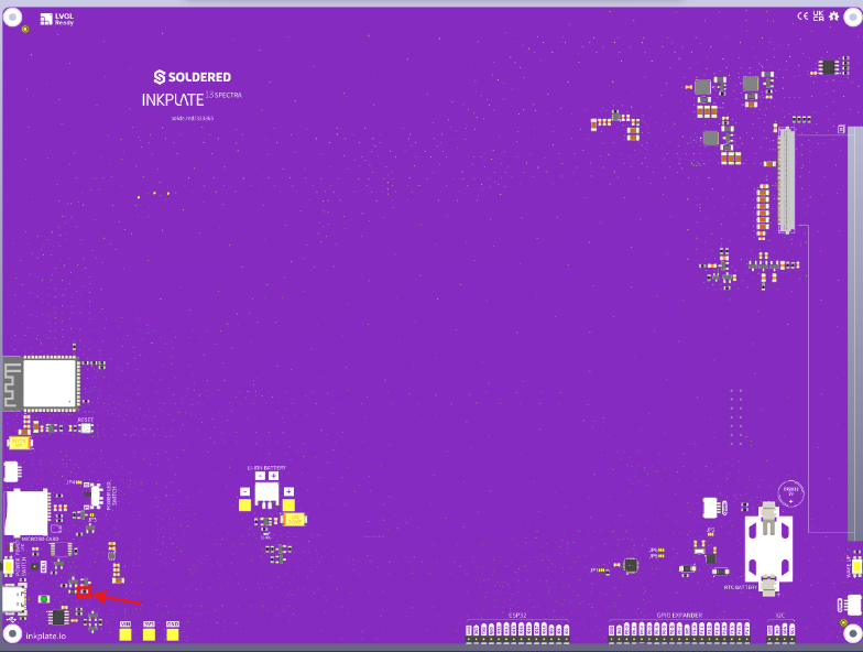
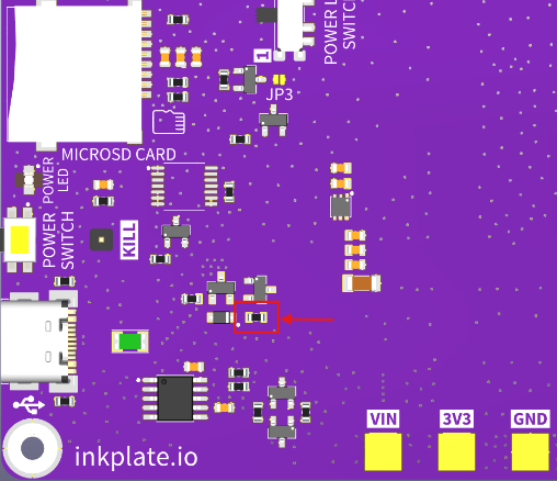
Ideally, could you mark them on a photo of the board or send a close-up showing the exact location of the R14 / bypass pads?

I don’t want to bridge the wrong pads, because the silkscreen around that area is not clear enough for me to identify R14 with confidence.

If possible, please also confirm:

  • whether those pads should simply be shorted with solder,

  • whether a 0 Ω resistor is preferred,

  • and whether shorting them guarantees automatic power-on whenever VIN is present after a complete power loss / fully discharged LiPo.

The board will be sealed inside an enclosure, so manual access to the power button will not be possible.

Hello @k_borek535

In the images below, I’ve marked resistor R14.

You can either bridge those two pads with solder or fit a 0 Ω resistor. Both give the same result: constant power regardless of the power switch position.