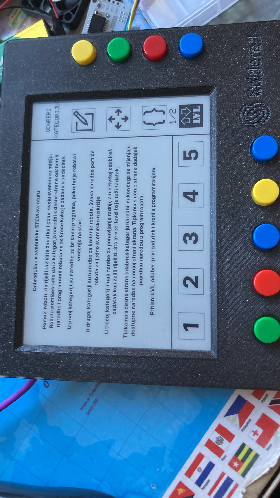
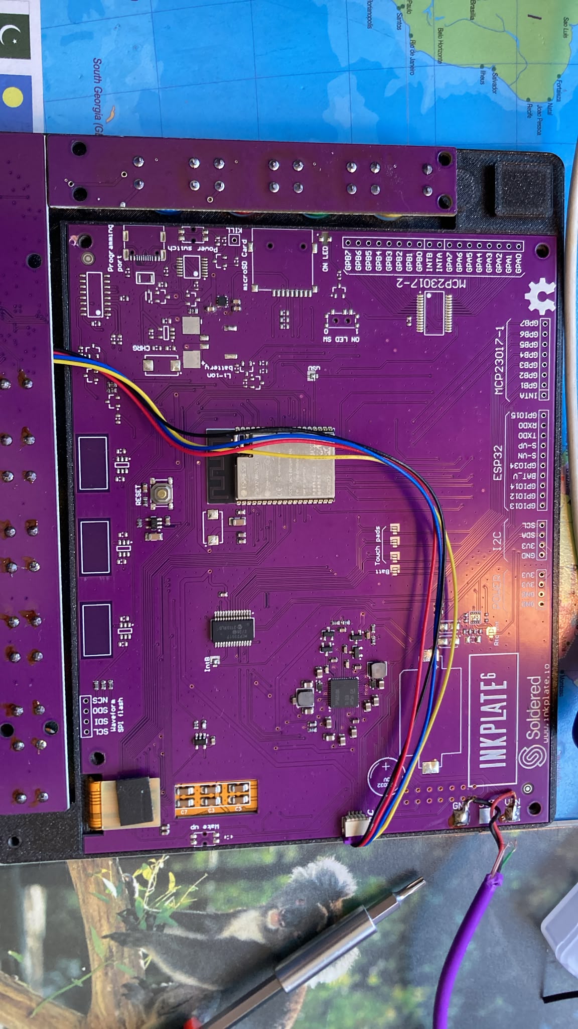
I have a Inkplate 6 with the CH340 and USB connector part completly strapped off. I managed to get it to post in the serial monitor using my Dasduino but it couldn’t upload. It works fine with this code that is uploaded on it(as shown in the picture), but i cant upload anything new to it.
This is the serial message:
��B@ďż˝k#��Bďż˝ ďż˝ ~Lďż˝1ďż˝)ďż˝ ��!9$!ďż˝1 ďż˝J0ďż˝ Ô 0���� L0N(J!!ďż˝LN)
���
�ets Jul 29 2019 12:21:46
rst:0x1 (POWERON_RESET),boot:0x12 (SPI_FAST_FLASH_BOOT)
configsip: 0, SPIWP:0xee
clk_drv:0x00,q_drv:0x00,d_drv:0x00,cs0_drv:0x00,hd_drv:0x00,wp_drv:0x00
mode:DIO, clock div:1
load:0x3fff0030,len:1324
ho 0 tail 12 room 4
load:0x40078000,len:13508
load:0x400804�ets Jul 29 2019 12:21:46
Hello @mario_pintaric ,
There doesn’t seem to be an image attached. Unfortunately, to flash the board, you also need to drive the GPIO 0 pin to low and the RST pin HIGH to achieve this. This is possible, but it does require some soldering, this way of programming also hasn’t been tested, but if you wish to pursue this I will make sure it is tested and i can guide you through the process.
Best regards,
JosipKuci
Looks like the images weren’t sent properly.
Here are the images:
Yes, my issue was that i couldn’t find GPIO 0 pin on the board. I first thought i can solder the CH340 and USB-C connector but i didn’t know would i still need GPIO 0. Do i need a programer or something similar?
Thank you for your awnsers
Best regards, Mario
Wow, thats a blast from the past project!
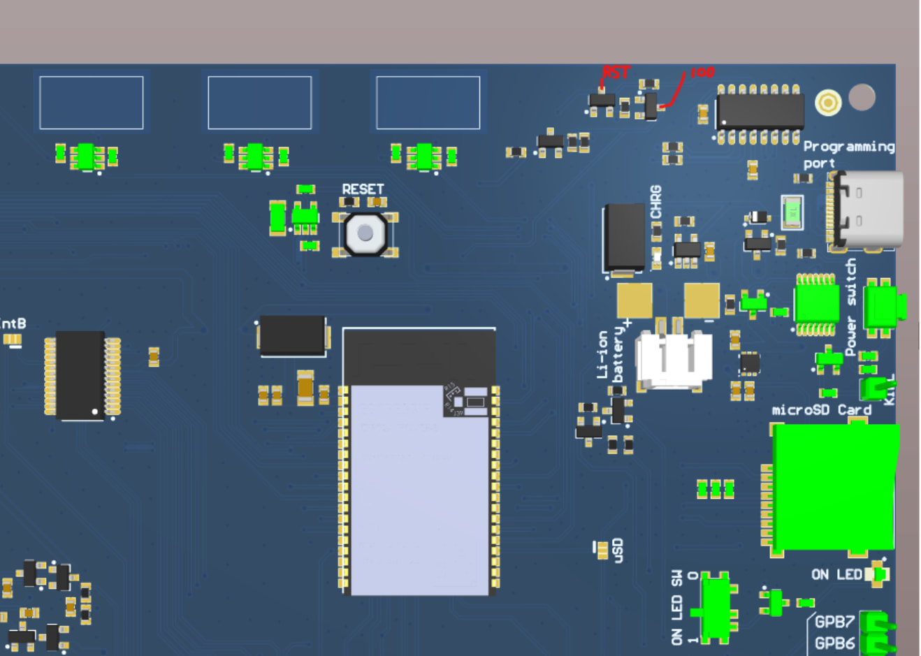
Since there is no CH340 chip onboard, it should be possible to program the board without an issue. Please solder wires to the following pads to do so:
There are two ways to program it:
-
You can use our ESP32 programmer, which is available here: ESP8266 & ESP32 USB Programmer for Easy Flashing – Soldered Electronics
-
You can use another esp32 device to program this one, I found this tutorial which may prove useful: https://medium.com/@adityabangde/flashing-firmware-to-an-esp32-using-another-esp32-d4798ddce70b
Let me know if there are any more questions!
So from what i understood, i just need the 2 voltage regulators that are labeled “RST” and “GPIO0”. Is that correct? Can you tell me a place where i can buy and solder those parts?
Thank you for your awnsers.
Best Regards,
Mario
No, you just need to solder wires to those metal pads under the transistors, they are connected internally to said GPIO pins.
Best regards,
JosipKuci
I tested it and it still got the same error and serial message as before.
I connected it like this:
Inkplate Dasduino CORE
TX RX
RX TX
GND GND
3v3 3v3
IO0 D2
RST D3
In Arduino IDE i selected ESP32 dev module and uploaded a blank sketch. Do i need to use an ESP32 device for it to work?
Best regards,
Mario