Croduino WiFi setup with ESP8266: firmware flashing and AT commands not working

Customer:

I’m building some prototypes with Arduino electronics and need help assembling an order. I have more background in programming than electronics and no experience with Arduino, so I have some additional questions.

To start, I’d like to build a standard module that takes input from any sensor and reports to a web server via WiFi module. Also, the web server should be able to communicate back to the module in both directions.

From your web shop, I’ve concluded I need the following:

BASE

I see it comes with a lot of things, but I assume it’s good for learning basic principles.

Questions:

How is the main board powered? Do I get an adapter in the package? Can it be powered via USB and is there a risk I’ll fry my computer?

Why do I need this component - isn’t Croduino compatible with Arduino shields?

PERIPHERALS

temp sensor (DHT11)

sound detector module

motion sensor (HC-SR501)

relay module (8-channel)

question: I want to control 220V but I see this is 150V?

COMMUNICATION

Bluetooth module (HC06)

WiFi - what’s the difference?

ESP8266 WiFi module

or Arduino WiFi shield?

what else do I need for 5V => 3.3V conversion?

Thank you for your help.

Original message (Croatian)

zelio bih raditi neke prototipove sa Arduino elektronikom pa bih molio malu pomoc kod sastavljanja narudzbe. Imam vise podloge u programiranju nego u elektronici, i nemam nikakva iskustva sa Arduinom tako da imam neka dodatna pitanja.

Za upoznavanje bi zelio sastaviti standardni modul koji kao ulaz ima bilo kakav senzor i preko WiFi modula javlja web serveru. Takoder osim sto cita da moze i obrnuto da se web server javlja modulu.

Preko vaseg web shopa zakljucio sam da mi treba sljedece:

BAZA

http://e-radionica.com/hr/croduino-set-za-pocetnike-csp-hobby.html . Vidim da tu dobivam puno vise stvari ali pretpostavljam da je dobro za upoznavanje osnovnih principa.

Pitanja:

kako se napaja glavna ploca? Dobijem li u paketu adapter? Dal moze preko USB-a i dal postoji opasnost da si spalim komp?

Zasto ova Soldered: Open-Source Electronics, Boards, Sensors & Modules – Soldered Electronics komponenta, zar croduino nije kompatibilan sa Arduino shildovima?

PERIFERIJA

senzor temp http://e-radionica.com/hr/dht11-senzor-temperature-i-vlage.html

detektor zvuka Soldered: Open-Source Electronics, Boards, Sensors & Modules – Soldered Electronics

senzor pokreta http://e-radionica.com/hr/senzor-pokreta-hc-sr501.html

relay Soldered: Open-Source Electronics, Boards, Sensors & Modules – Soldered Electronics

pitanje: zelio bih upravljati sa 220V a ovo je vidim 150V?

KOMUNIKACIJA

http://e-radionica.com/hr/bluetooth-modul-hc06.html

WIFI, koja je razlika?

Soldered: Open-Source Electronics, Boards, Sensors & Modules – Soldered Electronics

ili Soldered: Open-Source Electronics, Boards, Sensors & Modules – Soldered Electronics

sta mi jos dodatno treba za 5V => 3.3V

Hvala na pomoci.

Originally submitted via email support on 13 October 2015. Migrated to the forum for community visibility.

Soldered Support:

The CSP HOBBY is definitely a good choice for beginners with hardware experience who can program, especially with the additional sensors and modules. Among other things, there are numerous other electronic components included, so you won’t have to worry about missing anything while working on projects.

The board is powered via USB port, and the board has a fuse that protects both the board and your computer’s USB port - if you connect something incorrectly, nothing will happen. The fuse becomes functional again after a short time.

The board can also be powered with an external adapter voltage of 7-24V, connected to pins VIN (+ pole of adapter) and gnd (- pole of adapter).

For prototyping and learning, definitely use USB as the power source.

Croduino is 100% hardware and software compatible with Arduino, but their physical dimensions are not equal, so the Croduino to Arduino adapter is used to make it easier to attach Arduino shields to Croduino boards.

The sensors you listed will do what you need. As for the relay, there was an error in the description. They will handle 220V without any problem. Just, as always, be careful with high voltages!

For WiFi, the only difference is the shape of the board. The chip on it that performs the function is the same - ESP8266. You’ll need a logic level converter for proper conversion from 5V to 3.3V.

Original message (Croatian)

hvala Vam na upitu i povjerenju.
CSP HOBBY je definitivno dobar izbor za početnike sa hardwareom koji zna programirati, baš zbog dodatnim senzora i modula. Između ostalog su tu i brojne druge elektroničke komponente, pa se nećete morati brinuti da će Vam nešto faliti dok budete radili projekte.
Pločica se napaja preko USB porta, a na pločici se nalazi osigurač koji štiti i pločicu i Vaš USB port na računalu - u slučaju da Vi nešto krivo spojite, ništa se neće dogoditi. Osigurač ponovno postaje funkcionalan nakon kratkog vremena.
Pločica se može i napajati s vanjskog adaptera napona 7-24V, a priključuje se na pinove VIN(+ pol adaptera) i gnd(- pol adaptera).
Za prototipiranje i učenje, defitinivno koristiti USB kao izvor napajanja.
Croduino je 100% hardwareski i softwareski kompatibilan s Arduinom, ali njihove fizičke dimenzije nisu jednake, pa se Croduino na Arduino adapter koristi za lakše prikopčavanje Arduino shieldova na Croduino pločice.
Senzori koje ste nabrojali će Vam odraditi ono što trebate. Što se tiče releja, bila je pogreška u opisu. Oni će bez problema provesti 220V. Samo, kao uvijek, oprezno s visokim naponima!
Za WiFi, razlika je jedino u obliku pločice. Chip koji je gore i obavlja funkciju je isti - ESP8266. Trebat ćete još logic gate converter za ispravnu konverziju iz 5V na 3V3: Soldered: Open-Source Electronics, Boards, Sensors & Modules – Soldered Electronics
Ako imate još kakvih pitanja ili zapnete prilikom realizacije projekta, slobodno nam se obratite :slight_smile:

Hvala Vam;

Customer:

Thank you for the answers.

Regarding the Croduino to Arduino adapter - as I understand it, I only need it for shields that connect directly to the board. Modules (most sensors) I connect via breadboard? Are there any other practical differences between shields and modules in practice? Should I prefer one or is it just a matter of choice?

Regarding external power, do you have anything available?

Before I place an order, please confirm this is the right set for my needs:

BOARD

SENSORS

COMMUNICATION

ADDITIONAL

external power?

Thank you

Original message (Croatian)

puno hvala na odgovorima.

Vezano za Croduino=>Arduino adapter, koliko sam shvatio to mi samo treba za shildove koji se direktno spajaju na plocu, module (vecina senzora) spajam preko ekspertimentalne ploce? Jel postoji u praksi jos nekih razlika izmedu shieldova i modula? Trebam li preferirati ili je to samo stvar izbora?

Sto se tice vanjskog napajanja, dal imate nesto odmah raspolozivo?

Uglavnom, prije nego napravim narudzbu preko web shopa molim da mi potvrdite jel ovo set koji mi treba sukladno mom opisu.

PLOCA

http://e-radionica.com/hr/croduino-set-za-pocetnike-csp-hobby.html

SENZORI

http://e-radionica.com/hr/dht11-senzor-temperature-i-vlage.html

Soldered: Open-Source Electronics, Boards, Sensors & Modules – Soldered Electronics

http://e-radionica.com/hr/senzor-pokreta-hc-sr501.html

Soldered: Open-Source Electronics, Boards, Sensors & Modules – Soldered Electronics

KOMUNIKACIJA

http://e-radionica.com/hr/bluetooth-modul-hc06.html

Soldered: Open-Source Electronics, Boards, Sensors & Modules – Soldered Electronics

DODATNO

Soldered: Open-Source Electronics, Boards, Sensors & Modules – Soldered Electronics

Soldered: Open-Source Electronics, Boards, Sensors & Modules – Soldered Electronics

vanjskonapajanje?

Hvala

Soldered Support:

That’s correct. The C2A adapter is used only so Arduino shields can be connected directly to Croduino. They would otherwise work anyway, and the adapter just enables easier connection.

A shield is a board designed to be plugged directly into Arduino and function, while modules have various shapes and connect in various ways. It’s all a matter of choice; ultimately what matters is that everything actually works.

Unfortunately we don’t currently have any power supplies in stock right now - we’re experiencing a shortage of supplies. Otherwise we have something like this:

Otherwise you can take any power supply with voltage 7V - 24V and connect it to pins VIN and gnd.

Your component list is OK.

Feel free to get in touch if you get stuck; we’ll respond faster this time.

Original message (Croatian)

evo još jednom isprike zbog kašnjenja, bili smo out of office. Tako je, C2A adapter koristi se samo da bi se Arduino shieldovi mogli direktno spojiti s Croduinom. I inače bi oni radili, a adapter samo omogućava lakše spajanje. Shield je dakle pločica namijenjena da bi se direktno ukopčala u Arduino i funkcionirala, dok moduli imaju razne oblike i spajaju se na razne načine. Sve je stvar izbora, na kraju je bitno da zapravo sve funkcionira :slight_smile: Inače imamo ovako nešto: Soldered: Open-Source Electronics, Boards, Sensors & Modules – Soldered Electronics Inače možete uzeti bilokoje napajanje napona 7V - 24V i povezati na pinove VIN i gnd. Popis komponenti Vam je OK :slight_smile: Slobodno se javite ako zapnete, brže ćemo odgovoriti ovaj puta :slight_smile: [name removed]

Customer:

Is there an adapter for connecting to the pins of the WiFi module, or do I need to manually solder everything?

Original message (Croatian)

[name removed],

postoji li neki adapter za spajanje na pinove od wifi modula Soldered: Open-Source Electronics, Boards, Sensors & Modules – Soldered Electronics ili moram rucno sve lemiti?

Customer:

Also, I see that the TX pin from Arduino also needs to go through the logic converter to the RX of ESP8266. Can you give me more details about this? I’m using this module. What confuses me is the SDA and SLC pins. As I understand it, for serial communication it goes like this:

ASDA - analog 4

ASCL - analog 5

AVCC - TRX arduino

BSDA - nothing

BSCL - nothing

BVCC - RX esp

Original message (Croatian)

I dodatno pitanje, vidim da i TX pin iz Arduina moram preko logic konvertera spojiti na RX od ESP8266, jel mi mozes molim te dati vise detalja oko toga? To radim preko ovog modula Soldered: Open-Source Electronics, Boards, Sensors & Modules – Soldered Electronics , sad me je jedino buni SDA, SLC pinovi. Koliko sam shvatio ovako ide za serijsku kom?

ASDA - analog 4

ASCL - analog 5

AVCC - TRX arduino

BSDA - nista

BSCL - nista

BVCC - RX esp

Soldered Support:

Unfortunately there is no module, the ESP needs to be soldered manually. A board with the ESP module already soldered is in development.

For your other question: what you’ve written is for IIC (also called I2C or TWI) communication. For UART (also called serial communication), which is what you need for ESP, you connect according to the following table:

Croduino (A device) 3.3V device (B device)

AGND gnd -

ASDA tx -

ASCL rx -

AVCC +5V -

BGND - gnd

BSDA - tx

BSCL - rx

BVCC - +3.3V

So on side A you connect only Croduino, and on side B only ESP.

There are some additional pins on the ESP that need to be connected to HIGH or LOW. Have you found that?

Original message (Croatian)

nažalost ne postoji nekakav modul nego je ESP potrebno ručno lemiti. U razvoju je pločica koja na sebi ima već zalemljen ESP modul.
Za drugo pitanje; to što ste napisali je za IIC(još se zove I2C ili TWI) komunikaciju. Za UART(još se zove serijska komunikacija), a to Vam treba za ESP, spajate prema idućoj tablici:
CroduinoA uređaj) 3.3V uređaj(B uređaj)

AGND gnd -

ASDA tx -

ASCL rx -

AVCC +5V -

BGND - gnd

BSDA - tx

BSCL - rx

BVCC - +3.3V
Dakle, sa A strane spajate samo Croduino, a s B strane samo ESP.
Na ESPu je potrebno još neke pinove spojiti na HIGH ili LOW. Jeste li pronašli to?

Customer:

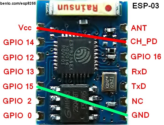
Thank you for the information. Yes, I connected the additional pins according to this image. Is that correct?

Also, does the ESP have an LED that signals it’s powered like the Bluetooth module does? Because it looks completely dead and doesn’t respond to Arduino over serial communication. It’s possible I burned it during soldering, although I think I did it pretty neatly and there are no visible physical damages.

By the way, when are you planning to release Croduino with ESP?

Original message (Croatian)

Hvala na informacijama. Da, spojio sam dodatne pinove po ovoj slici http://benlo.com/esp8266/ESP-03-pinout1.jpg. Jel to tocno?

Inace, jel ima ESP LEDicu sa kojom signalizira da je pod napajenjem kao npr. bluetooth modul? Jer izgleda mi totalno mrtav niti ne odgovara Arduinou preko serijske kom. Moguce da sam ga spalio prilikom lemljenja, makar mislim da sam dosta uredno to napravio i ne vide se fizicka ostecenja.

Btw kad planiras izbaciti Croduino sa ESP?

Soldered Support:

According to the image, everything is OK.

Unfortunately there’s no LED that indicates power is connected properly. You probably connected it correctly, but the ESP is a bit “tricky” until you establish communication with it for the first time. What you need to do is change its default baud rate. I recommend this guide: https://medium.com/@nowir3s/getting-started-with-esp8266-875fb54441d6#.w5ikoblg4

You probably didn’t burn the ESP, you just haven’t established communication with it yet.

Croduino with ESP is currently in prototype form, and soon the printed boards will go into production. Overall it could be around a month, and while we prepare materials for work it might be a bit longer. Sign up for the newsletter for sure, as soon as the announcement comes, the newsletter will have it too.

Original message (Croatian)

prema slici je sve OK.
Nažalost nema LEDicu koja indicira da je napajanje OK spojeno. Vjerojatno i jeste dobro spojili, ali malo je “zeznut” taj ESP dok prvi puta ne uspostavite komunikaciju. Ono što trebate napraviti je promijeniti njegov default baud rate. Preporučam ovaj guide: https://medium.com/@nowir3s/getting-started-with-esp8266-875fb54441d6#.w5ikoblg4
Vjerojatno niste spalili ESP, samo niste još ostvarili komunikaciju s njime.
Croduino s ESP je trenutno u obliku prototipa, a uskoro će tiskane pločice u proizvodnju. Sveukupno bi moglo biti oko mjesec dana, a dok pripremimo materijale za rad možda i malo više. Prijavite se na newsletter svakako, čim bude objava, bit će i newsletter :slight_smile:

Customer:

I can’t get the ESP to work at all. I managed to flash the firmware or at least partially because it often crashes. I’m trying via “esptool.py” for example:

./esptool.py --baud 4800 --port /dev/cu.usbserial-AI029ST9 write_flash 0x000000 esp8266_at/bin/boot_v1.1.bin 0x01000 esp8266_at/bin/newest/user1.bin 0x7C000 esp8266_at/bin/esp_init_data_default.bin 0x7E000 esp8266_at/bin/blank.bin

The first 2 files work but the others won’t.

Similarly, I can’t get the ESP to return anything sensible and respond to AT commands - it always outputs garbage in the serial console. No matter which baud rate I set. Regarding the Arduino program, does it need to have some program that acts as a proxy between Croduino and ESP, or does Croduino need to have a blank sketch loaded? Flashing only works for me when Arduino has a blank sketch loaded. But after going back to “run mode” it doesn’t respond to AT commands at all and throws garbage in the console.

Most tutorials on the web use USB-TTL for communication and I haven’t received mine by post yet. Did you send it by post and to which address?

Original message (Croatian)

[name removed],

nikako da upogonim taj ESP do kraja, uspio sam flashati firmware ili barem djelomicno jer mi cesto puca. Pokusavam preko “esptool.py” npr.

./esptool.py --baud 4800 --port /dev/cu.usbserial-AI029ST9 write_flash 0x000000 esp8266_at/bin/boot_v1.1.bin 0x01000 esp8266_at/bin/newest/user1.bin 0x7C000 esp8266_at/bin/esp_init_data_default.bin 0x7E000 esp8266_at/bin/blank.bin

pa mi prva 2 fajla prodju ostali nece.

Isto tako nikako ne mogu dobiti da mi ESP vraca nesto smisleno i da odgovara na AT komande, uvijek izbacuje neko smece u serial consoli. I to kojigod baud rate postavim. Sto se tice Arduino programa dal mora imati neki programa koji glumi kao proxy u komunikaciji izmedu croduina i esp ili croduino mora imati ocitan blank sketch? Sto se tice flashanja samo mi radi kad arduino ima blank sketch loadan. Ali isto tako nakon vracanja u “run mode” uopce ne odgovara na AT i baca smece u consoli.

Vecina tutoriala na webu koristi USB-TTL za komunikaciju a meni jos nije stigao postom? Dal si poslao postom u pon i na koju adresu?

Soldered Support:

I haven’t tried flashing the ESP yet, all I’ve done with it is connect it to the net and ping Google to see that it’s actually connected - and that’s it. I should take a bit of time with it towards the end of next week and play around with it, so see how to flash and do something more with it (I have to do that anyway for our new product), but I can’t before that because I have to finish some other projects.

The USB-TTL adapter is actually the Croduino itself and works in the identical way you connected it. It has a USB-TTL (UART) bridge which can be accessed through digital pins 0 and 1. The only difference is that they also come to the ATmega, but if the sketch on it doesn’t have a “Serial.begin(baud);” method, there shouldn’t be a problem - i.e. it doesn’t matter which sketch is on the ATmega as long as the serial communication class with the begin method is not initialized.

Garbage in the Serial is a sign of wrong baud rate. Did you perhaps set the baud to a value that doesn’t even exist in Arduino Serial Monitor?

Regarding the USB-TTL adapter and 2x C2A adapters, they have been sent, but our post office in Osijek made something up. All our packages are late, apparently our packages were left somewhere with a side error. We called, they said they would fix it, that the packages would be delivered by mid-next week. They didn’t tell us what it was about.. Sometimes it goes like that with Croatian Post, unfortunately, and we don’t have an alternative to them (couriers are too expensive for some things).

Original message (Croatian)

nisam još probao flashati ESP, sve što sam stigao s njime je povezati se na net i pingati Google da vidim da je stvarno spojen - i to je to.. Krajem idućeg tjedna bih ga trebao malo uzeti i poigrati se, pa vidjeti kako flashati i nešto više napraviti s njime(to ionako moram za naš novi proizvod), a prije ne mogu jer neke druge projekte moram dovršavati.
USB-TTL adapter Vam je zapravo i Croduino i to na identičan način na kojega ste ga i spojili. Na njemu se nalazi USB-TTL(UART) bridge kojemu je moguće pristupiti preko digitalnih pinova 0 i 1. Jedina razlika je što tu dolaze i na Atmegu, ali ako se na njoj nalazi sketch u kojemu nema “Serial.begin(baud);” metode, problema ne bi trebalo biti – tj. nije bitno koji sketch je na Atmegi sve dok nije inicijalizirana klasa za serijsku komunkaciju s metodom begin.
Smeće u Serialu je znak krive baud brzine. Jeste li možda podesili baud na neku vrijednost koja uopće ne postoji u Arduinovom Serial monitoru?
Što se tiče USB-TTL adaptera i 2x C2A adaptera, poslano je, ali naša pošta u Osijeku je nešto zeznila. Svi paketi nam kasne, valda su naše pakete negdje greškom ostavili sa strane. Zvali smo, rekli su da će riješiti, da će sredinom sljedećeg tjedna paketi biti dostavljeni. Nisu nam rekli o čemu se radi.. Tako to nekada ide s Hrvatskom Poštom, nažalost, a neku alternativu za njih nemamo..(kuriri su preskupi za neke stvari)

Adresa na paketu je..

[name removed] 16,[address removed],[address removed] je OK?